
In the field of modern high-performance engines, turbocharging technology lets small-displacement engines deliver much more power than expected. The key part that makes this possible is an important part of the turbocharger – the turbine impeller.
The turbine impeller’s working environment means it needs to spin at high speeds: 100,000 to even 200,000 revolutions per minute. It also has to withstand exhaust gas temperatures of over 900°C. At the same time, it needs to keep a very complex aerodynamic shape to ensure air flow efficiency. This poses an extreme challenge to its manufacturing process: How to make an impeller that is both extremely complex and extremely strong?
The answer is: investment casting. This is also the core technology that QD Casting Factory has focused on for many years.
Scientific Material Selection – How to Choose the Right Material
The turbine impeller first faces the ultimate test of materials. It is continuously exposed to exhaust gas at 800-1000℃. At the same time, it endures centrifugal force of 200,000 revolutions per minute. Ordinary stainless steel would have already softened, deformed or even melted in this environment. It is completely unable to handle the job. So, what material should we choose?
Main Choice: High-Nickel-Based Superalloys
Currently, high-nickel-based superalloys like Inconel 713LC are the main materials for making turbine impellers.
They have two key advantages:
- High-temperature strength (heat strength): Under continuous high temperatures, they still maintain extremely high mechanical strength. They resist “creep” deformation. This ensures the impeller keeps its size stable during long-term high-speed operation.
- Heat fatigue resistance: The impeller needs to withstand thermal cycles. These cycles go from normal temperature to high temperature, with repeated sudden cooling and heating. High-nickel-based alloys can effectively resist alternating stress caused by thermal expansion and contraction. This prevents cracking.
Cutting-Edge Trend: Lighter and Stronger Titanium-Aluminum Alloys
To pursue higher turbocharging response speed (that is, to reduce turbine rotational inertia), lighter materials have become a research and development direction. Titanium-aluminum alloys are intermetallic compounds. Their density is only about half that of nickel-based alloys. But they have excellent strength and temperature resistance. But, their casting difficulty is extremely high. They have extremely strict requirements for smelting and cooling control.
| Material Type | Maximum Temperature Resistance | Core Advantages | Challenges | Application Scenarios |
| Ordinary Stainless Steel | ≤600℃ | Low cost Easy to process | Poor high-temperature strength Prone to creep | Ordinary mechanical parts under low temperature and low pressure |
| High-nickel-based superalloy (e.g., Inconel 713LC) | ≤1050℃ | High high-temperature strength Excellent thermal fatigue resistance | Relatively difficult to process High inertia | Mainstream turbocharger impellers |
| Titanium-aluminum alloy (TiAl) | ≤850℃ | Density is only 60% of nickel-based alloys Significant lightweight advantage | Prone to cracking during casting High brittleness | High-performance racing cars New energy turbine impellers |
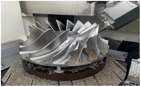
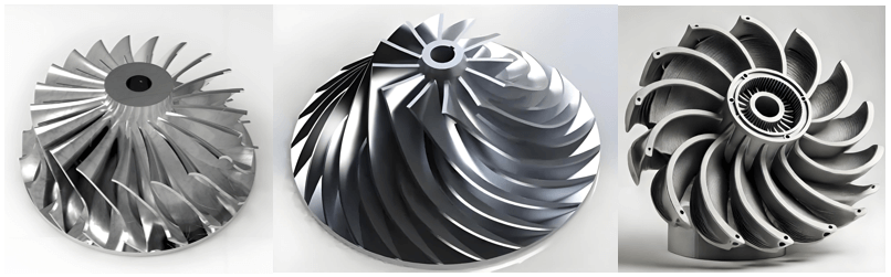
Precision Forming – Complex Aerodynamic Surfaces
The precision of the turbine impeller’s blade profile, twist angle and thickness directly determines turbocharging efficiency and airflow noise. The essence of investment casting lies in “replication”. It can convert every detail in the CAD model into a metal entity without the slightest error.
1. Ultra-High Dimensional Precision
The wax patterns made by 3D printing can have their dimensional tolerance controlled within ±0.1mm. This ensures that the profile and twist angle of each blade are exactly the same as the design model. This means airflow can flow along the optimal path. It avoids efficiency loss caused by dimensional deviations.
Through precision molds and strict process control, QD Factory can control the tolerance within ±0.15mm, or even tighter. This is the foundation for ensuring the impeller’s aerodynamic performance.
2. Excellent Surface Finish
Airflow friction causes energy loss. So the impeller surface must be as smooth as a mirror. If there are protrusions or roughness on the impeller surface, it will increase airflow friction loss. It will also reduce turbocharging efficiency.
We use extremely fine zircon powder as the surface ceramic material. We match it with a silica sol binder. This way, we make molds with extremely high smoothness. After mold making, the surface roughness (Ra) of the casting can be as low as 1.6μm. This reduces airflow resistance to the greatest extent.
3. Addressing the Challenges of Complex Structures
The gaps between impeller blades are narrow. This makes it easy to have problems: ceramic slurry can’t fill the gaps completely, or cracks appear when drying. Some high-performance impellers have blade gaps of only 2-3mm. Traditional mold-making processes easily face issues: ceramic molds can’t be filled fully, or cracks form.
QD has many years of experience and know-how. It optimizes slurry viscosity, sand particle size and drying environment. This ensures the integrity and strength of ceramic molds in complex structural parts.
QD optimizes the fluidity of ceramic slurry and the number of coating layers. It also combines the segmented drying process. This ensures narrow gap areas are completely filled. It also ensures the mold strength meets the required standards.
Internal Quality: Pursuing “Zero Defects”
When the impeller rotates at high speed, even tiny shrinkage porosity inside it (that is, small holes formed when metal solidifies) may expand into cracks under centrifugal force. This can cause safety accidents. The ultimate challenge of investment casting is solving internal shrinkage porosity. This is also the core technology of QD Casting.
Simulation First: Prediction and Optimization
Before pouring metal, we use professional simulation software such as Magma/ProCAST. It fully reproduces the filling and solidification process of molten metal on the computer. This can accurately predict the areas where shrinkage cavities and shrinkage porosity may occur. Thus, we optimize the design of the gating system and the cooling plan. This reduces the occurrence of defects at the source.
Application of Directional Solidification Technology: Guiding the Solidification Sequence
By controlling the temperature field of the mold, we make the molten metal solidify sequentially. It solidifies from the impeller’s hub (the thick-walled part) to the blades (the thin-walled parts). When the thick-walled part solidifies first, it shrinks. At this time, the molten metal in the thin-walled parts (still liquid) can replenish it in time. This avoids the formation of shrinkage porosity. This technology increases the internal density of QD impellers to over 99.5%.
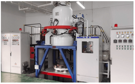
HIP Hot Isostatic Pressing Treatment
Even with precision control, there may still be microscopic shrinkage porosity inside the casting. HIP is a crucial post-process. The impeller is placed in a high-pressure argon furnace. It is kept in an argon environment at a high temperature of 1100℃ and a high pressure of 150MPa for a certain period of time. This process is like “kneading metal”. It causes microscopic plastic deformation of the metal. It also presses and welds the tiny internal holes closed. This greatly improves the material’s density, fatigue life and reliability. It increases the material’s fatigue life by more than 30%. It completely eliminates hidden risks of internal defects.
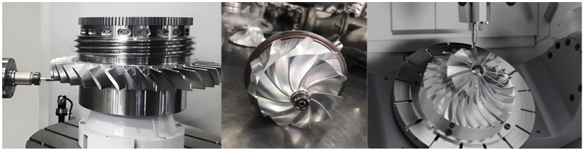
Ultimate Testing: From Blank to Finished Product
High-precision finishing: QD uses 5-axis CNC lathes and CNC grinders. It processes key fitting parts of the impeller, such as shaft holes and end faces. This ensures the fitting accuracy between the impeller and the turbine shaft. It avoids vibration caused by fitting gaps.
Ultra-high speed dynamic balance correction: The impeller must undergo dynamic balance testing at ultra-high speed (much higher than the working speed). QD uses professional dynamic balance testing equipment to detect unbalance. It corrects by removing a tiny amount of material with laser. This ensures the balance accuracy reaches G0.4 level.
100% Non-Destructive Testing (NDT):
- X-ray inspection: 100% X-ray scanning is done on the impeller. It checks for shrinkage cavities and cracks inside.
- Penetrant Testing (PT): It uses fluorescent penetrant to detect micro-cracks on the impeller surface. These micro-cracks are hard to see with the naked eye. It checks for micro-cracks on the surface and near-surface.
Not Just Casting, But a Commitment to Performance
QD Casting can steadily deliver high-performance turbine impellers. This is because it is committed to combining cutting-edge materials with advanced processes. From material selection to simulation optimization and then to non-destructive testing, every step is strictly controlled.
If your product is facing challenges of high complexity and high performance requirements. Whether it is used in the aviation, racing or industrial fields. Welcome to contact QD. We look forward to cooperating with you.
FAQ
1. What is the minimum wall thickness of impellers made by investment casting?
With advanced investment casting technology, QD Factory can stably produce turbine impellers. The minimum wall thickness of these impellers can reach 0.8-1.0 mm.
2. How do you ensure consistency in mass production?
We achieve consistency control through three methods. First, we fix material batches. Second, we standardize process parameters. Third, we conduct mechanical property tests on samples from each batch. These tests include high-temperature tensile tests and fatigue tests.
3. Besides nickel-based alloys and titanium-aluminum alloys, can you handle other materials?
Yes, we can. We are also good at handling other materials. These materials include various stainless steels, cobalt-based alloys and aluminum alloys. We can recommend the most suitable solution according to your specific performance requirements.
4. Is HIP treatment necessary?
For turbine impellers working in high-speed and high-stress environments, HIP treatment is strongly recommended.It can significantly improve fatigue life and reliability.
5. Can you customize turbine impellers of special specifications based on our CAD model?
Yes, you can. QD has a professional team of process engineers.They can conduct simulation analysis, process design and customized production based on the 3D model provided by the customer.
6. What is the design life of the impeller?
For nickel-based alloy impellers, the regular design life is 80,000-100,000 kilometers (for automotive applications).For aerospace applications, it can reach more than 5,000 hours.Specifically, it can be adjusted according to working conditions.